Is it possible to erase the firmware of an ESP32 from within itself? Let’s try to find out.
You might ask yourself: why do you even need a function like that? - I mean… why not?
If you want to erase the ESP32’s flash content, the easiest way would be using esptool.py with the erase_flash parameter. But how we can do this from within the running Arduino Sketch?
Early attempts and Ideas
First of all, I needed to familiarize myself with the flash layout and partitions of the ESP32. I had already used Over The Air (OTA) Updates1 and SPIFFS Filesystem2 before. It was nothing new to me, but like everyone else, I used ready built libraries for that.
So, how can I read and write to the flash chip of the ESP32? After reading through a few pages of the Espressif Documentation3 I tried out some tests on the ESP32 Simulator Wokwi.com, so as to not damage my physical hardware. (In case I do something totally wrong.)

Using the esp_partition_erase_range(), esp_flash_erase_chip() and esp_flash_erase_region() functions always ended up with the same result. The ESP32 crashes when it tries to remove the partition or region where the firmware itself is running. Makes sense, right?
After wasting an entire evening, I went to bed, where my close to autism spectrum brain still couldn’t rest and tried to come up with new solutions thus blocking me from sleeping.
Then there was this moment where my old school wannabe criminal VX noobie past kicked in: What if the main firmware (dropper) encapsulates the sub firmware (stub) like a virus and executes it from RAM memory and deletes everything on the flash? Could that be the answer? Maybe, but can I program something like that? Nah!
Before I finally fell asleep, I had the idea to look into the source codes for Over The Air Updates.
Over The Air Updates under the Hood
So, the main problem is that you can’t (easily) overwrite the partition the firmware is running on. But how does the OTA Update replace the current with the latest firmware? I started digging into the Update.h library of the ESP32 and try to understand the Arduino example sketches.
In easy words: The OTA process copies the new firmware to a second partition app1 (ota_1) and if everything was successful, the ESP32 sets a boot flag on the second partition and deactivates the first partition app0 (ota_0). After restarting the ESP32, the bootloader selects the partition app1 instead of the default app0 and starts the updated firmware.
There is only one little tiny issue: I don’t want to send the firmware over the air (via network). fortunately, this is where the SPIFFS storage partition comes handy.
Self-Destruction in two Stages
To try this idea, I wrote two separate programs. A main (Stage 1) and a stub firmware (Stage 2). The job of the stub firmware is to erase everything on the flash and the job of the main firmware is to start the stub firmware from the SPIFFS partition when the self-destruction function is triggered.
I used a button with internal pull-up on Pin 32 to trigger the self-destruction function.
Feel free to trigger the self-destruction function via WiFi, ESP-NOW, LoRa, Bluetooth or some kind of Timer. (Your own creativity is the limit here. If you have some crazy ideas let me know about it.)
Stage 1 - Main Firmware
1
2
3
4
5
6
7
8
9
10
11
12
13
14
15
16
17
18
19
20
21
22
void init_update() {
  File file = SPIFFS.open("/stub.bin");
  if (!file) {
    Serial.println("Failed to open file for reading");
    return;
  }

  size_t filesize = file.size();

  if (filesize > 0) {
    Serial.println("Try to start update");
    // pass the stub.bin to the OTA update
    perform_update(file, filesize);
  } else {
    Serial.println("Error, file is empty");
  }

  file.close();

  // remove the payload stub.bin in second stage.
  // SPIFFS.remove("/stub.bin");
}
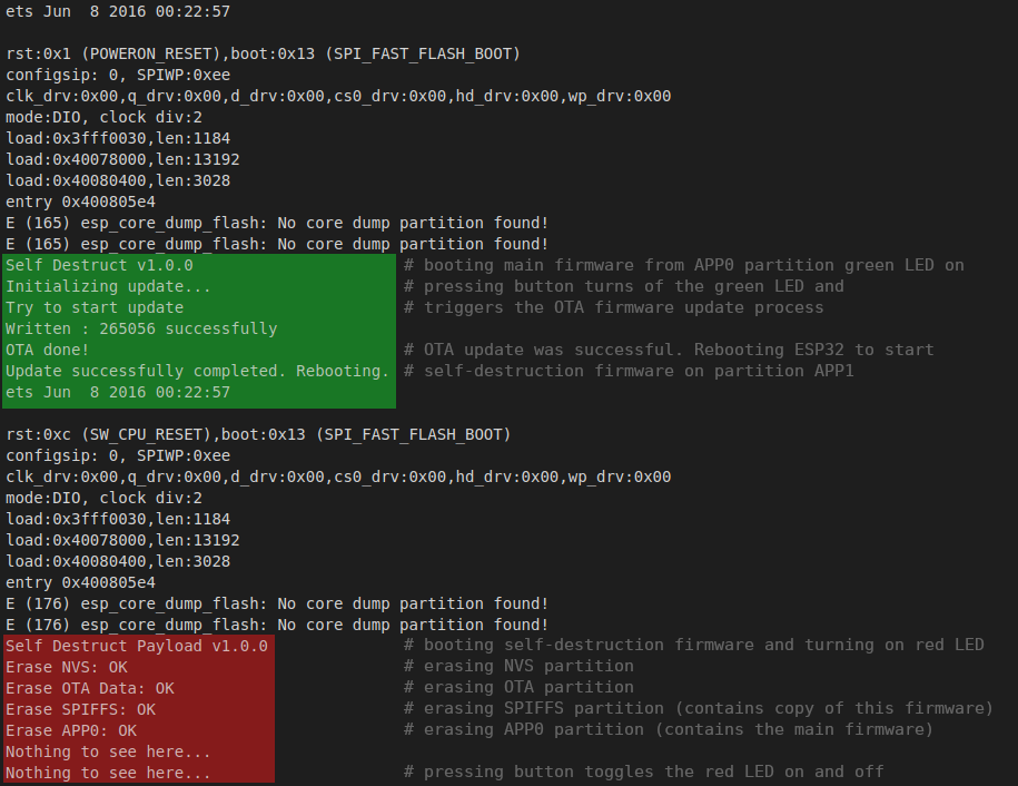
As soon the button is pressed, the green LED on Pin 25 turns off and the OTA Firmware Update process starts reading the stub.bin file from the SPIFFS partition. If the update process was successful the ESP32 restarts and goes into stage two.
Stage 2 - Stub Firmware
The stub firmware, let’s you know it is active and running by turning on the red LED on PIN 26 and starts erasing the all partitions (except app1). After finishing the operation it turns off the red LED.
1
2
3
4
5
6
7
8
9
10
11
12
13
14
15
16
17
18
19
20
21
22
23
24
25
26
27
28
29
30
31
32
33
34
35
36
// erase everything except the own partition (APP1) to avoid crashing
Serial.print("Erase NVS: ");
if(esp_flash_erase_region(NULL, 0x9000, 0x9000) == ESP_OK) {
  Serial.println("OK");
} else {
  Serial.println("ERR");
}

Serial.print("Erase OTA Data: ");
if(esp_flash_erase_region(NULL, 0xe000, 0x2000) == ESP_OK) {
  Serial.println("OK");
} else {
  Serial.println("ERR");
}

Serial.print("Erase SPIFFS: ");
if(esp_flash_erase_region(NULL, 0x290000, 0x160000) == ESP_OK) {
  Serial.println("OK");
} else {
  Serial.println("ERR");
}

Serial.print("Erase APP0: ");
if(esp_flash_erase_region(NULL, 0x10000, 0x140000) == ESP_OK) {
  Serial.println("OK");
} else {
  Serial.println("ERR");
}

// uncommenting this part would crash the ESP32
// Serial.print("Erase APP1: ");
// if(esp_flash_erase_region(NULL, 0x150000, 0x140000) == ESP_OK) {
//   Serial.println("OK");
// } else {
//   Serial.println("ERR");
// }
Demo Screenshot
The green part highlights the main firmware (Stage 1) and the red part the stub firmware (Stage 2).
Partition layout of usual Firmware
| Offset | Before Update | After Update |
|---|---|---|
| 0x9000 | NVS | NVS |
| 0xe000 | OTA |
OTA |
| 0x10000 | APP0 (Firmware) | APP0 (Firmware disabled) |
| 0x150000 | APP1 (Empty) | APP1 (New Firmware actived) |
| 0x290000 | SPIFFS (Empty) | SPIFFS (Empty) |
The OTA process itself does not delete the old firmware. If stage 2 wouldn’t erase the app0 partition, the main firmware would still be at the same place 0x10000 and it could be easily recovered by a third party.
By erasing everything the only recoverable firmware is the stub firmware itself that still remains on the app1 partition.
Partition layout of Self-Destructing Firmware
| Offset | Before Update | After Update | After Erase |
|---|---|---|---|
| 0x9000 | NVS (Data) | NVS (Data) | NVS (Empty) |
| 0xe000 | OTA |
OTA | OTA (Empty) |
| 0x10000 | APP0 (Firmware) | APP0 (Firmware disabled) | APP0 (Empty) |
| 0x150000 | APP1 (Empty) | APP1 (Stub Firmware actived) | APP1 (Stub Firmware) |
| 0x290000 | SPIFFS (Stub Firmware) | SPIFFS (Stub Firmware) | SPIFFS (Empty) |
To verify if the self-destruction was successful, dump the flash content of the ESP32 via esptool.py. Assuming your device is connected to port /dev/ttyUSB0 and the entire 4MB flash content gets dumped into the files before_erase.bin and after_erase.bin.
1
2
3
4
$ # dump flash content before self-destructing is triggered
$ esptool.py --chip esp32 --port /dev/ttyUSB0 --baud 921600 read_flash 0 0x400000 before_erase.bin
$ # dump flash content after self-destructing is triggered
$ esptool.py --chip esp32 --port /dev/ttyUSB0 --baud 921600 read_flash 0 0x400000 after_erase.bin
You can now compare the two binary files by preparing it like this:
1
2
3
$ hd -v before_erase.bin > before.txt
$ hd -v after_erase.bin > after.txt
$ meld before.txt after.txt # You can also use diff or colordiff
As you can see we got rid of everything except the stub firmware’s partition. I’m happy and I can live with that.
Privacy
By erasing, writing and reading from the flash of the ESP32, I found my system digital fingerprints. File paths, including username are embedded into the firmware binary.
I try to use xtensa-esp32-elf-strip to get rid of it, but it didn’t help much. Going down the rabbit hole I found Reproducible Builds4 but this is something for another time.
My advice is to compile the project on a virtual machine or inside a docker container and check with a hex editor or grep if any sensible information remains in the binary file.
I don’t know if digital forensics experts can still recover overwritten parts of the partitions through some crazy expensive ways, but for extreme paranoia people, you can try to overwrite the flash chip additionally with random bytes.
Bonus
Here is a snippet to overwrite the (NVS) partition with something else other than 0xFF:
1
2
3
4
5
6
7
8
9
10
11
12
13
14
15
16
17
18
// overwrite the NVS partition with 0xAA instead of 0xFF

const esp_partition_t * partition = esp_partition_find_first(ESP_PARTITION_TYPE_DATA, ESP_PARTITION_SUBTYPE_DATA_NVS, NULL);

void* ptr = malloc(partition->size);
if(ptr == nullptr) {
  Serial.println("Error malloc");
  return;
}

memset(ptr, 0xAA, partition->size);

esp_err_t err = esp_partition_write(partition, 0, ptr, partition->size);
if(err != ESP_OK) {
  Serial.println("Error overwriting NVS");
}

free(ptr);
Sources
The entire project including the source code for Stage 1 and Stage 2 can be downloaded on GitHub.
Shout-out and thanks to Yusuf Coşgun (REevee0). After asking on Discord about ideas and suggestions, he came up with the same idea in few minutes, meanwhile I wasted days in my mind palace searching for a solution.
He also came up with the idea to use SPIFFS storage. This saved me a lot of low-level work and programming.